39 rectifier regulator wiring diagram
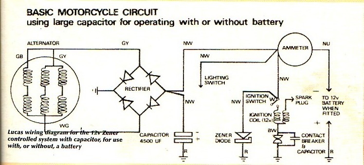
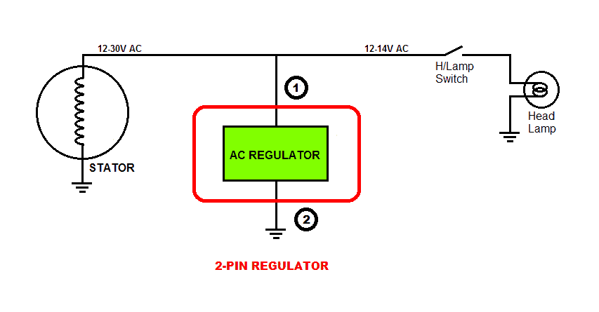
Kohler Rectifier Wiring - Wiring Diagram Pictures Wiring is a 3 wire flat with the 2 outside wires being the AC Voltage coming from stator and middle wire is for battery voltage. Understanding Motorcycle Voltage Regulator Wiring ... 1) 2-pin Regulator: This type may be found on some small bicycles which do not have battery and only have Head Lamp & Tail Lamp. Since the incandescent bulbs work well on AC voltage, there is no rectifier section in this type of regulator. The circuit inside the unit regulates the AC voltage coming from the generator to 13.5 - 14 VAC for the bulbs.
Rectifier Regulator Wiring Diagram | Snow and Mud Home Rectifier Regulator Wiring Diagram ippielb Feb 16, 2016 1 2 Next Feb 16, 2016 #1 ippielb Active VIP Member Joined Mar 4, 2011 Messages 1,745 Reaction score 2,542 Location SE Saskatchewan Website Bought a 12v rectifier regulator to put on my sled to change the 12v AC into 12v DC for my air fuel gauge.
Rectifier regulator wiring diagram
Motorcycle Regulator Rectifier Wiring Diagram - Collection ... Motorcycle Regulator Rectifier Wiring Diagram Source: cdn5.fast-serve.net MUST-KNOW TIPS FOR DIY ELECTRICAL WIRING IN ADDITION TO SWITCHING 1. Have the right tools handy Just like any other DIY job, you want to ensure you have the right tools to do the job. bike regulator rectifier circuit diagram - Wiring Diagram ... Bike Regulator Rectifier Circuit Diagram. 3 phase motorcycle voltage regulator circuits homemade circuit projects understanding wiring universal rectifier electrical for and boat motors diy engines online in taiwan b07l94ntsb tester building a electronics forums honda cg125 150 zj125 at affordable s free shipping real reviews with photos joom ... Rectifier Regulator Wiring Diagram For 150cc Chinese - Wire How to wire a gy6 scooter regulator rectifier and how it all works part 3 the regulator. Rectifier regulator wiring diagram for 150cc chinese. If you find that your electrical system overloads when you rev up the machine then you most likely need to replace the voltage regulator. Here are a couple of photos of the carter 150cc gy6 rectifier.
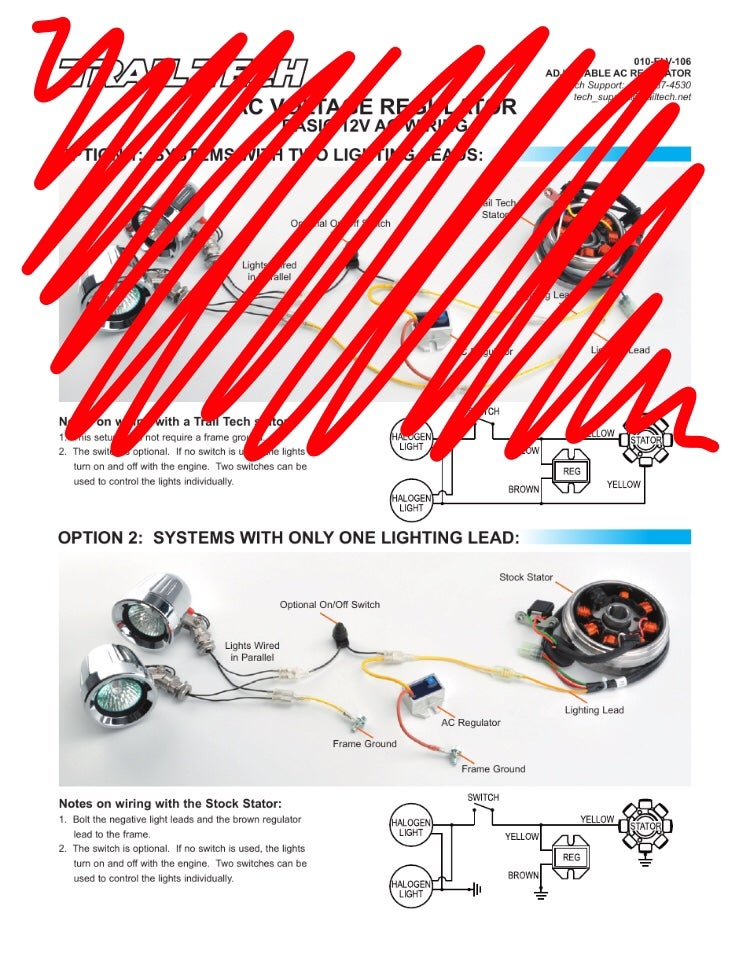
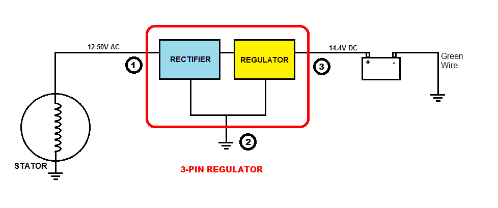
Rectifier regulator wiring diagram. PDF Regulator/Rectifier Wiring Guide Reg/Rec Wiring Using ... REGULATOR/RECTIFIER WIRING GUIDE 010-ELV-116 Tech Support: (844) 378-8143 technicalservice@apexproductgroup.com REG/ REC +-BA TTE LIGHT RY LIGHT RED SWITCH YELLOW YELLOW STATOR BLACK RED/YELLOW ADJUSTING REG/REC VOLTAGE DIAL: 1. Remove blue paint from adjustment dial marked "Voltage" (Fig. 2.) 2. Use a #1 Phillips, adjust "Voltage" dial ... 6 Wire Regulator Rectifier Wiring Diagram 6 Wires Motorcycle Regulator Rectifier Plug Voltage Regulator … The best other is always to use a verified and accurate 6 wire regulator rectifier wiring diagram that's provided from a trusted source. A good, standard company that has a long track book of providing the most up-to-date wiring diagrams easy to use is not difficult to find. Alternator Voltage Regulation 101 (with Wiring Diagrams ... A typical 3-wire alternator wiring diagram with an internal voltage regulator. Computer-Controlled Voltage Regulation. Many late-model vehicles use the engine computer, which is often referred to as the powertrain control module (PCM), to control alternator output. Most modules use an internal driver to turn the alternator's field circuit on ... Rectifier Regulator Wiring Diagram - Wiring Schemas Rectifier regulator wiring diagram. You'll need access to a wiring diagram for the make and model your regulator rectifier is off. However it doesnt mean link between the cables. Locate and remove the zener diode. 1) three wires originating from the alternator charging phases.
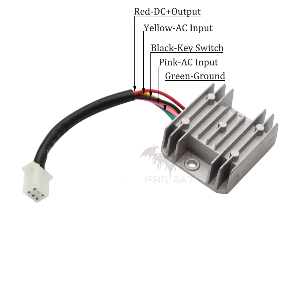
Pitbike Rectifier/Regulator Wiring Diagram - YouTube In this video, I show how to wire the rectifier/regulator to the stator of the pitbike. I show how to make connections for the headlight. I also show how to ... Wiring diagram for separate regulator/rectifier. | Yamaha ... Scroll down the post listed belowand there will be one by Skull that has stock diagrams. They look about postage stamp size but get larger when you click them. They are all right out of the box Yamaha diagrams and will give you an idea of how to hook up the separate regulator and rectifier combination. Polaris Voltage Rectifier Regulator Wiring Diagram Polaris Voltage Rectifier Regulator Wiring Diagram old wires Brown Yellow/Red Red White Black Green The Polaris diagram identifies the regulator as being located on the elect. panel where the rectifier are open, causing high "ripple" or A/C voltage (while charging volts and amps are still. Rectifier Regulator Signal Wires - Rick's Motorsport ... Many Rick's Motorsport Electrics Rectifier/Regulators eliminate what is commonly referred to as a "signal wire" on original equipment (OE) pieces. For example, on a 1981 Kawasaki KZ440 , there are 5 wires going to the OE part: 2 yellow wires (AC inputs), white/red (DC "+" output), black/yellow (DC "-" output), and a brown wire.
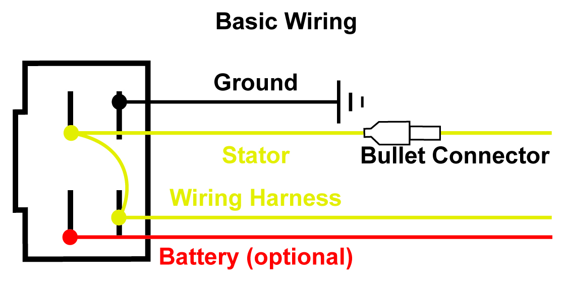
Recitifer Regulator Signal Wires - Rick's Motorsport ... Recitifer Regulator Signal Wires. Many Rick's Motorsport Electrics Rectifier/Regulators eliminate what is commonly referred to as a "signal wire" on OE pieces. For example, on a 1981 Kawasaki KZ440, there are 5 wires going to the OE part: 2 yellow wires (AC inputs), white/red (DC "+" output), black/yellow (DC "-" output), and a ... Links [ ] Honda CB 750 K1 Wiring Schematics This wiring schematics diagram is key in finding out how the charging system works on the Honda CB750 K1. It will help address issues in relation to the regulator rectifier and the stator of this motorcycle PDF Rex's 12 Volt Solid State Regulator Rectifier: RR12V-14 battery as shown in the basic wiring diagrams. 3. Connection at the rectifier wiring In all cases the old rectifier is removed. It is entirely possible to connect your new solid state unit at the wires here. In fact if the machine has an ammeter doing so ensures the ammeter shows a charge. Using this point makes a neat job of wiring in the new ... Rectifier Regulator Wiring Diagram | Page 2 | Snow and Mud ... Here's my stator diagram, and here's what they do at the ECU. I don't want to pull current from something and have it give me a weak spark and run like crap, and i don't want to fry another ECU. So if the charge coil #2 puts out 85-94v AC, un regulated. And i add the rectifier regulator tapping into the Brown&White wire, and the Red&Green wire.
4 wire / 5 wire regulator rectifier wiring diagram and Explain Regulator (TAGALOG)
Briggs and stratton voltage regulator diagram Briggs And Stratton Voltage Regulator Diagram. If the battery will not charge the fault may be the battery rectifier diode regulatorrectifier or stator. Briggs and stratton voltage regulator briggs and stratton stator briggs and stratton alternator. Briggs and Stratton VOLTAGE REGULATOR.
Trail tech regulator/rectifier - KTM 2 Stroke - ThumperTalk
Sh586b-12 Wiring Diagram Connect the battery negative (-) cable to an engine mounting bolt, frame bolt, or other good engine ground connection. Check the battery cable connections to.The borrowed rectifier (SH) seems to be very similar to what Honda calls for on my engine (SHB). Except that the one rating is a little lower @ 8A instead of 10A.
Understanding Motorcycle Voltage Regulator Wiring - Homemade ...
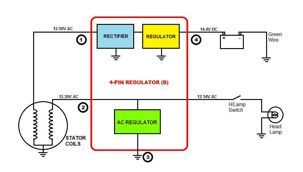
12 volt 4 pin regulator rectifier wiring diagram The schematic is rather easy to understand. Aftermarket replacements are available but can be expensive. 12 Volt Wiring Diagram Best 12v Relay Pin 5 and Roc Grp org In. Jul 28, 2018 - 12 Volt Generator Voltage Regulator Wiring Diagram Wiring diagram also offers helpful recommendations for tasks that may require some additional equipment. The rectifier actually converts the power from AC to DC ...
External voltage regulator wiring diagrams for alternators ...
How to wire a 4 wire voltage regulator rectifier - YouTube Chinese voltage regulator wired up to honda gx clone with charge coils.
Replacing rectifier/regulator with regulator all in one ...
Polaris Voltage Rectifier Regulator Wiring Diagram studying the wiring diagram a bit more, i can see that elec start sleds.polaris virage voltage regulator rectifier $ polaris virage voltage regulator rectifier $ polaris big boss 6x6 regulator rectifier $ polaris sportsman 4x4 regulator rectifier $ polaris sportsman ho 4x4 regulator rectifier $ polaris sportsman voltage regulator diagram ~ …
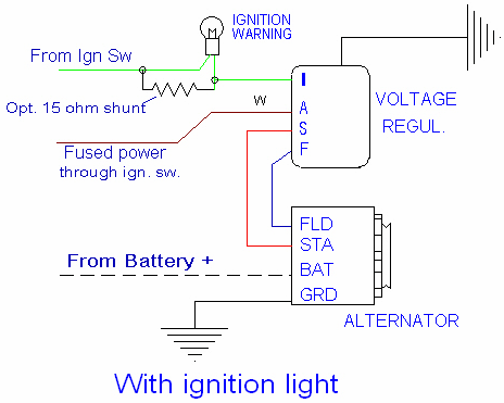
Regulator Wiring Diagrams
Motorcycle Regulator Rectifier Wiring Diagram | Wiring ... Rectifier Regulator Wiring Diagram - 12v rectifier regulator wiring diagram, atv regulator rectifier wiring diagram, honda regulator rectifier wiring diagram, Every electrical structure is made up of various unique parts. Each component should be set and linked to other parts in specific way. Otherwise, the structure won't work as it should be.
CHECK_THIS_OUT_!!!!! NEW__A WAY_BETTER_WAY TO WIRE IN A 6 OR ...
Rectifier Regulator Wiring Diagram For 150cc Chinese - Wire How to wire a gy6 scooter regulator rectifier and how it all works part 3 the regulator. Rectifier regulator wiring diagram for 150cc chinese. If you find that your electrical system overloads when you rev up the machine then you most likely need to replace the voltage regulator. Here are a couple of photos of the carter 150cc gy6 rectifier.
Common-Motor Regulator/Rectifier? | Honda Twins
bike regulator rectifier circuit diagram - Wiring Diagram ... Bike Regulator Rectifier Circuit Diagram. 3 phase motorcycle voltage regulator circuits homemade circuit projects understanding wiring universal rectifier electrical for and boat motors diy engines online in taiwan b07l94ntsb tester building a electronics forums honda cg125 150 zj125 at affordable s free shipping real reviews with photos joom ...

On Alternator External Voltage Regulator Wiring Diagram ...
Motorcycle Regulator Rectifier Wiring Diagram - Collection ... Motorcycle Regulator Rectifier Wiring Diagram Source: cdn5.fast-serve.net MUST-KNOW TIPS FOR DIY ELECTRICAL WIRING IN ADDITION TO SWITCHING 1. Have the right tools handy Just like any other DIY job, you want to ensure you have the right tools to do the job.

4-Wire Full Wave Motorcycle Regulator Rectifier 12V DC Bike Quad Scooter | eBay
Voltage Regulator Upgrade: Help Needed| Motorcycles and ...

Lovely Wiring Diagram Alternator #diagrams #digramssample ...
Understanding Motorcycle Voltage Regulator Wiring - Homemade ...
Wiring Solid state Single phase Regulators | JRC Engineering ...
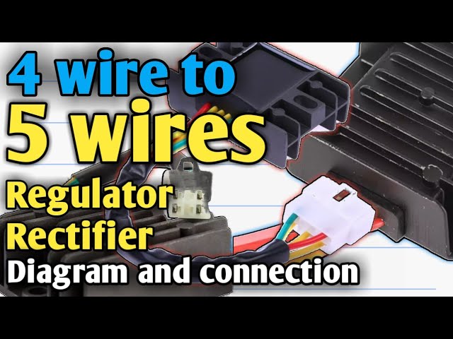
4 wires to 5 wires Regulator rectifier Paano ang connection ...

6 Wire Universal 12 Volt Regulator Rectifier - Rex's Speed Shop

Wiring a Bosch Voltage Regulator | if you have a bosch ...

Motorcycle Regulator Diagram and Amazon: Wires V Voltage ...
Old Biker Bert's British Bike site

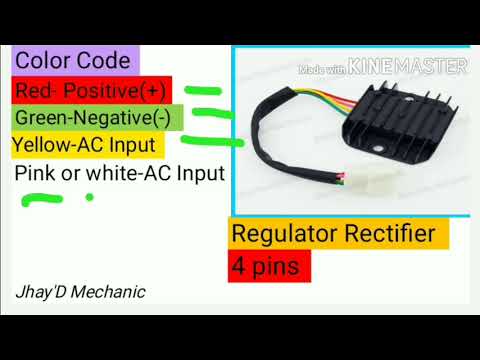
RECTIFIER REGULATOR 5-PIN/ DIFFERENCE COLORS

Yamaha XS650 Parts & Vintage Yamaha Parts - MikesXS.com

Australian Land Rover Owners
916 Regulator replacement | Ducati.ms - The Ultimate Ducati Forum

1969 Mach1 Voltage Regulator Wiring | Vintage Mustang Forums
Understanding Motorcycle Voltage Regulator Wiring - Homemade ...

Building a regulator/rectifier for a motorcycle | Electronics ...
Kawasaki EL250, GPX250, GPZ250, ZR400R, EN450, EN454 Regulator Rectifier - RR14
Motogadget M-Unit & Ricks Regulator/Rectifier Help | Cafe ...
Alternator/Regulator troubleshooting
Understanding Motorcycle Voltage Regulator Wiring - Homemade ...

rectifier-regulator-wiring-diagram | Husaberg Wiki
5 Wires Voltage Regulator Rectifier For Gy6 125cc 150cc 200cc ...

Kawasaki Voltage Regulator Wiring Diagram & Answers To Common ...
Wire from regulator rectifier, which terminal does it go on ...
Regulator Wiring Diagrams
Alternator Wiring

Universal MOSFET regulator rectifier

CHARGING SYSTEM WIRING DIAGRAM WITH EXTERNAL VOLTAGE ...
Wiring diagram for separate regulator/rectifier. | Yamaha ...


Comments
Post a Comment