40 tortoise switch machine wiring diagram
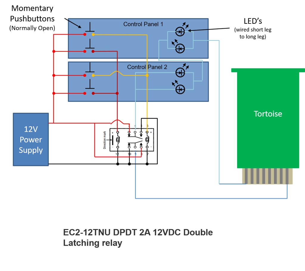
Wiring a DPDT switch with a Tortoise and 2 LED - janbouli.com Wiring a DPDT switch with a Tortoise and 2 LED Someone asked me how I wired my DPDT switches to my Tortoises so the LED's on my control panel would change the lighted color. This is my attempt at a tutorial. You will need , a DPDT switch On-On , 2 LED's 1 red 1 green is what I use, a piece of heat shrink tube and 3 colors of wire. ... .037" Diameter Throwbar Wire For Tortoise™ Switch Machines The wire that should have been included with your Tortoise ™ switch machine!. The wire that is included with Tortoise switch machines is 0.022" in diameter. While this works OK for commercial turnouts that have not been installed and ballasted, it can prove to be a bit flimsy for hand laid switches once they are installed and ballasted in place.
Tortoise Switch Machine Wiring Tortoise (Stall Motor) Machines. Electrically: 12 VDC. DPDT Switch. Stall Motor. Continuous low current (~20 ma) allows light wiring. 20 ma ideal to power. Switch point and signal wiring using the internal switches on the Tortoise™ switch machine If all your TORTOISES™ are mounted facing the same way, you can eliminate the terminal block ...

Tortoise switch machine wiring diagram
Installing a Tortoise - Model Railroad Academy The assembly on the Tortoise Slow-Motion Switch Machine is very minimal. One arm needs to be slipped in place and the throw arm will need to be bended. The throw arm that comes with the product is adequate for HO scale or for shallow roadbed, but most modelers opt to use heavier steel wire. George offers suggestions if you wish to modify the arm. PDF No Fail Tortoise Instructions - makemytracks.com No Fail Tortoise Installation Instructions The Tortoise switch motor is popular among modelers because it is sturdy, reliable, and operates in a slow, prototypical fashion. You can watch your turnout point rails move slowly, just like the real thing. And the motor may be used in any application where an electrically Need a wiring diagram for a tortoise machine, Re: Need a wiring diagram for a tortoise machine, Author: SP4360. You would be better off using a DPDT center off toggle switch set up like a standard reversing switch. The outside terminals are the motor leads of the tortoise if you didn't already know. I would suggest using a 5 volt dc wall wart as power for slow movement.
Tortoise switch machine wiring diagram. Tortoise - Circuitron The CIRCUITRON R emote T ortoise™ M ount consists of a molded base mechanism to which the Tortoise ™ (not incl uded) is mounted. An adjustable lever arm is fastened onto the Tortoise ™ output and drives a stainless steel wire inside a flexible teflon tube, much like a sub-miniature choke cable. This thin wire attaches to a compact actuator mechanism and is mounted beneath the turnout. Tortoise point motor wiring | Resources | Scalefour Society Wiring up a Tortoise motor is best done in two stages. Start by wiring up a DPDT switch which will control the direction of the motor. Connect a power supply to C and D Connect F and A plus a feed to the point motor. Connect E and B plus a feed to the point motor. Next, wire the tortoise itself. The Tortoise has 8 terminals. Tortoise Switch Machine Wiring Diagram - autocardesign Tortoise Switch Machine Wiring Diagram - wiring diagram is a simplified within acceptable limits pictorial representation of an electrical circuit. It shows the components of the circuit as simplified shapes, and the faculty and signal friends in the company of the devices. A wiring diagram usually gives guidance virtually the relative ... Tortoise Switch Machine Wiring Harness - How It's Done ... In This Episode of How It's Done, we will see how to make a wiring harness for the Circuitron Tortoise Switch Machine. I also give a brief description of the...
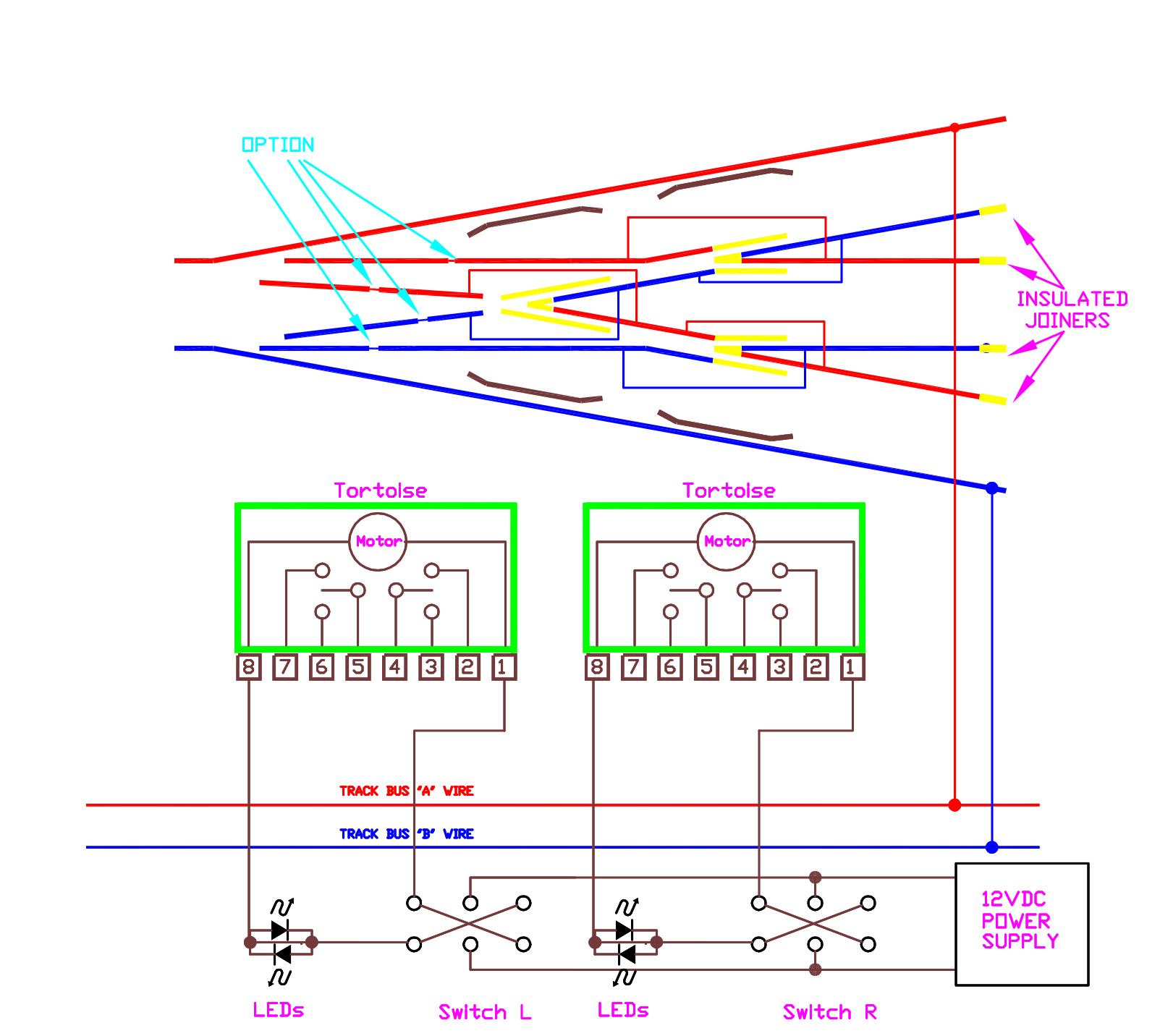
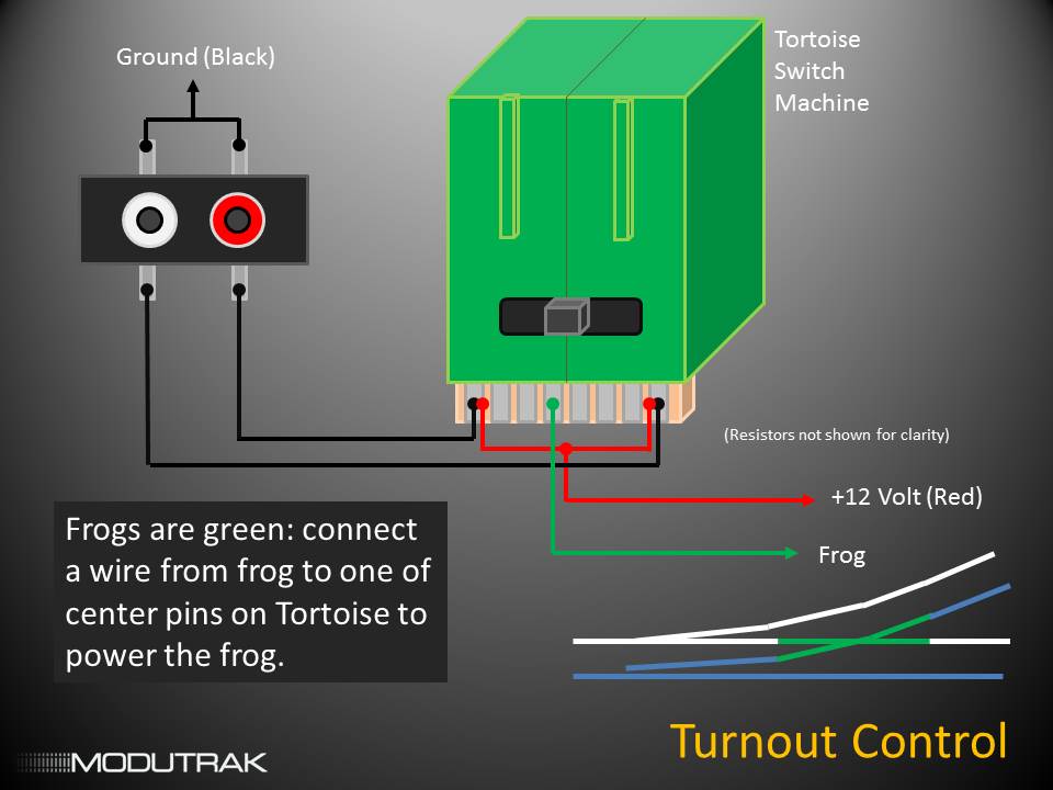
PDF CONGRATULATIONS - Circuitron TORTOISE will draw 15-16 ma. at stall, so 30 switch machines can be powered by a single 9 or 12 volt, 500 ma. wall plug adapter (available from Radio Shack). Any type of DPDT switch (toggle, slide, etc.) can be used to switch the polarity. This system will have two wires running from the control panel to each TORTOISE. See Diagram 1 below. 2. Tortoise Switch Machine Easy-Wire Adapters - Berrett Hill Shop Connect Tortoise switch machines to our Touch Control System or any other without solder! Stripped wires from 14 gauge to 22 gauge firmly connect with just a screwdriver to wire-clamping screw terminal connections. A sturdy socket with gold plated slide-on contacts pushes easily onto the Tortoise PC board. Wiring Tortoise switch machines. - the MRH Forum Hello! I was asked by a close friend to install and wire two Tortoise switch machines to operate a crossover in his layout, but I am not familiar with the wiring of those switch machines for that purpose. To set both turnouts for their respective normal routes (i.e., to run trains parallel) or when set for a train to cross over from one track to the other, the Tortoises are supposed to be ... Wiring Turnouts - Wiring for DCC Tortoise Diagram. Step 1: Connect a red wire to Tortoise terminal #2, a blue wire to terminal #3, and a green wire terminal #4. (Since frogs are green, your frog wire should be green, too!) ... Step 3: Install your Tortoise switch machine and get it working. Install your LEDs and get them working correctly on your control panel.
1006 / SNAPS! Wiring Connector for Tortoise Switch Machine ... Wiring Connector for Tortoise Switch Machine -- 12V pkg(6) (Scale = All) #107-1006. Accu-Lites SNAPS! is an easy wiring connector for the Tortoise Slow Motion Switch Machine. It is composed of a connector that SNAPS onto the Tortoise and an eight-position wiring block for wiring up the Tortoise. Includes special stay-put shims. Wiring Tortoise Switch Machines Circuitron tortoise wiring diagram wiring diagram is a simplified agreeable pictorial representation of an electrical circuit it shows the components of the circuit as simplified shapes and the faculty and signal friends together with the devices. Wiring tortoise switch machines. Wiring Dwarf signals to a Tortoise switch machine? - Model ... The # 1 and 8 leads from the Tortoise are wired to a DPDT switch. The other two wires from the DPDT switch are wired to the AC side of the transformer. The # 7 lead from the Tortoise is wired to the AC side of the transformer. The # 5 and 6 leads from the Tortoise are wired to LEDs with an in line resistor soldered on one leg of each LED. Circuitron Tortoise Wiring Diagram Circuitron Tortoise Wiring Diagram. They provide further clarification (and in some cases, wiring diagrams) of 01 or , referring to notes specific to the AR-1 and TORTOISE™. A thin, precise, laser-cut plastic template for use when multiple TORTOISE™ switch This thin wire attaches to a compact actuator mechanism and is mounted. 20 ma ideal ...
Southern Pacific Cascade Line: BACK TO BASICS
Tortoise Switch Machine Wiring - Wiring Diagram Pictures May 09, 2018 · SNAPS! is a wiring connector for the Tortoise Slow Motion Switch Machine. It is composed of an edge connector that SNAPS onto the Tortoise and an 8 position terminal block for wiring the Tortoise. Terminal block accepts wire from #14 - 22 AWG.5/5 (10). For Circuitron Model Train Electronics, Trust Tony's Trains.

Switch-8 | Manualzz
Tortoise switch machine wiring to led's, turnouts and ... A video on how to properly wire a tortoise switch machine, control panel led's, a turnout and 3 turnout signals and operate them with a dpdt toggle switch.
model railway wiring
PDF Switch Machines Installation & Wiring - Palmetto Div Tortoise (Stall Motor) Machines Electrically: 12 VDC DPDT Switch Stall Motor Continuous low current (~20 ma) allows light wiring 20 ma ideal to power LED In series with Tortoise Relatively long throw, continuous force while power on Slow, realistic turnout motion Two sets reliable SPDT contacts •Carry 4 amps, switch 1 amp •Frog power, signals, panel lights, etc
Switch Machines Installation & Wiring
Wiring A Tortoise Switch Machine for the Mainline - LAMRS Feb 27, 2010 · Build the Power Module, Appendix 3, and then pre-wire the Tortoise connector with Power and Frog connections. An alternate LED and Power Module are described in Appendices 4 and 5. These are for use with the Tortoise Remote Mount. 1.1 Let’s Start You are replacing an existing mainline switch machine whose electrical connections are proper, but
Wiring for Dcc - Peco switches
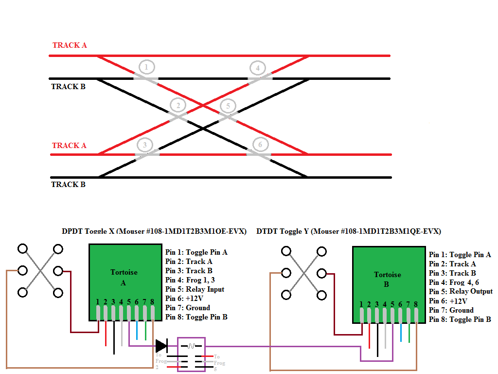
Wiring a tortoise switch machine to control a crossover ... Make a common wire from the + of one and the - of the other to one side of the tortoise. Connect the other side of each power supply to the DT portions of the switch. Once again run the SP connection of the switch to the other side of the tortoise. These directions and diagrams for each should have been in the tortoise box.
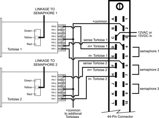
KB920: Installing Semaphore Type Signals with SE8C
PDF Tortoise Wiring/LED Clinic To Panel Switch Wiring Panel LEDs in Series with the TORTOISE Switch Machine Green LED Irzz,'iaa 271 RocBaar Drive Romeoville, IL 60446 (815) 886-9010 12345678 Note: Do not use additional resistors. The resistance of the TORTOISE motor is about 600 ohms, an ideal limiting resistance for LEDs.

Tortoise Switch Machine Wiring | Model railroad, Switch ...
switch wiring - the MRH Forum Tortoise Switch Machine Wiring Diagram. Hi, Here is a rendering we made up that shows with colour coded wires how to wire a simple turnout with a Tortoise machine. This will result in a DC or DCC friendly turnout with a live frog. This uses a simple DPDT switch to reverse the switch machines polarity and change the switch direction.
Wiring a double cross over: How to info - Model Railroader ...
Tortoise Switch Machine Wiring Dcc - schematron.org Nov 25, 2018 · The TORTOISE™ Slow Motion Switch Machine is the most popular and respected switch machine in the US. 3 second throw, bulletproof stall motor design, DPDT contacts, simple under-layout installation. And for the DCC user. Tortoise LEDs (optional) (indicate switch position SPDT switch Use two power supplies w/ Common ground Makes wiring much ...

Wiring advice LEDS, resistors and slide switches - Model ...
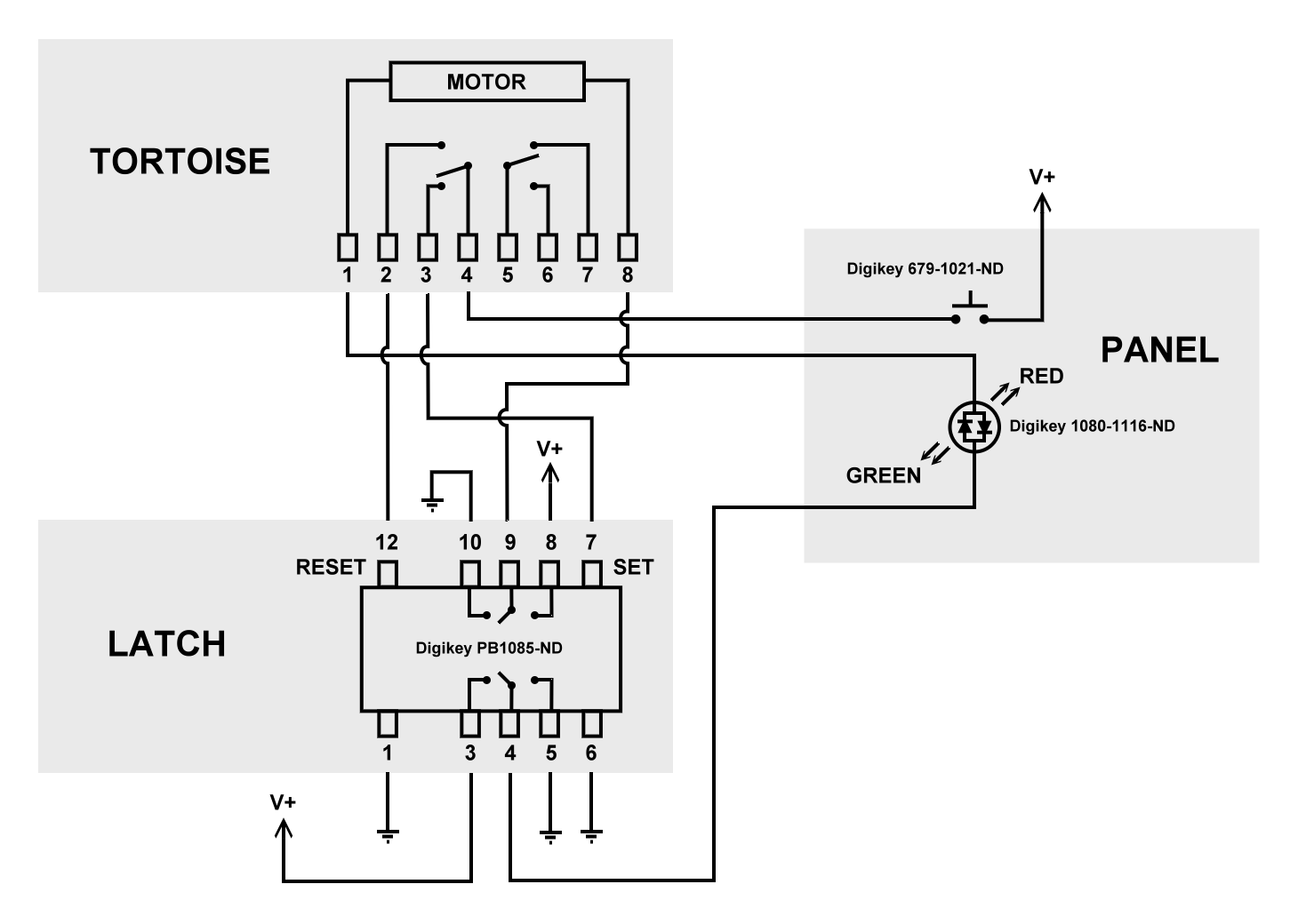
Magazine Article: Matrix Control for Tortoise Switch Machines Matrix Control for Tortoise Switch Machines. ... The basic circuit is shown above as a wiring diagram and below as a schematic. Essentially, the asymmetrical power supply is just a center-tap transformer—one that is normally used to create a simple half-wave plus/minus DC supply—with one of the end terminals, and not the center tap, used as ...

Diode Matrix Systems
Walthers New DCC Compatible Turnouts - Wiring for DCC 2. Connect your power routing switch or switch machine to your bus as shown in the above drawing. If the locomotive shorts when it goes across the frog, swap the wires that connect your power routing switch or switch machine to your bus. 3. Run a wire from each point rail to the corresponding bus wire as shown in color above. 4.
Build Manual: Module Wiring Standards | Modutrak Forums
Tortoise Point Motor Wiring Diagram - schematron.org 6 Comments. on Tortoise Point Motor Wiring Diagram. Switch point and signal wiring using the internal switches on the Tortoise™ switch If all your TORTOISES™ are mounted facing the same way, you can. movement of the points and a clear area under the layout for mounting the machine. . detailed wiring diagrams of turnout frog, relay and ...

Tam Valley Depot
PDF Wiring Diagrams for New Dwarf Signals - MoreLEDS.com Below is a wiring Diagram for use with Tortoise Switch Motors Note: when used with a tortoise no resistors are needed. Below is a diagram for use with a Tortoise Switch Motor using our BiLevel 3mm leds at the trackside and a Bippolar red/green led at your control panel. ... for switch machine and snap relay Momentary Twin Coil Switch Machine

Switch-It C.pdf - DCC Concepts
Need a wiring diagram for a tortoise machine, Re: Need a wiring diagram for a tortoise machine, Author: SP4360. You would be better off using a DPDT center off toggle switch set up like a standard reversing switch. The outside terminals are the motor leads of the tortoise if you didn't already know. I would suggest using a 5 volt dc wall wart as power for slow movement.

http://www.dccspecialties.com/products/tortoise/signal-wiring ...
PDF No Fail Tortoise Instructions - makemytracks.com No Fail Tortoise Installation Instructions The Tortoise switch motor is popular among modelers because it is sturdy, reliable, and operates in a slow, prototypical fashion. You can watch your turnout point rails move slowly, just like the real thing. And the motor may be used in any application where an electrically

Signals for your Model Railroad
Installing a Tortoise - Model Railroad Academy The assembly on the Tortoise Slow-Motion Switch Machine is very minimal. One arm needs to be slipped in place and the throw arm will need to be bended. The throw arm that comes with the product is adequate for HO scale or for shallow roadbed, but most modelers opt to use heavier steel wire. George offers suggestions if you wish to modify the arm.
Tam Valley Depot
Operating Tortoise Motors from Two Sides of a Layout - Model ...

Tortoise switch wiring | Model Train Forum
Turnout Control

65. Pre-wire your Tortoise Switch Machines for Easier, Faster Installations

How to wire Circuitron Tortoise Point Motors - Model Railway ...

Wiring Tortoise Switch Machines - Electrics (non-DCC) - RMweb

Average Model Railroader: Switch machine standards
Tortoise Machine Installation... | Page 3 ...

WIRING DIAGRAMS FOR MODEL RAILROADS - HOW TO HOOK UP LEDS ...
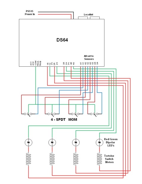
DS64 Wiring Drawing (for Train Controller program to throw ...

Examples of track-plans
Switch Machines Installation & Wiring
Untitled Page
How To Wire A Standard Turnout With A Ground Throw (And How ...
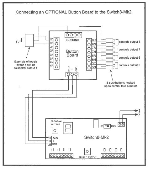
Switch 8 Mk2 – Welcome to the NCE Information Station
LCC and Tortoises
Magazine Article: Matrix Control for Tortoise Switch Machines
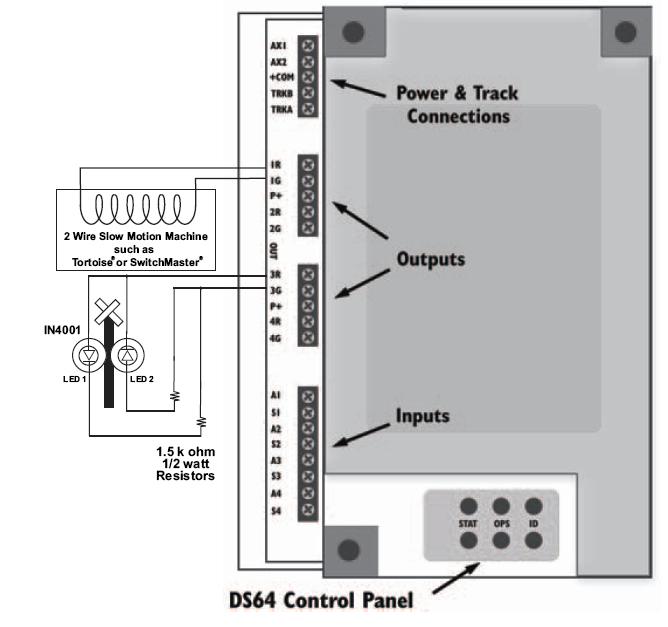
KB807: DS64 - Slow-motion turnout machines & crossing gates

tortoise slow motion switch machine
![NCE 5240151 Switch-8 MK2 will control 8 Tortoise Switch Machines [Accessory DCC Decoder]](https://cdn.shopify.com/s/files/1/0520/1972/4454/products/nce-5240151-switch-8-mk2-will-control-8-tortoise-switch-machines-accessory-dcc-decoder-2_608x700.png?v=1618598570)
NCE 5240151 Switch-8 MK2 will control 8 Tortoise Switch Machines [Accessory DCC Decoder]
Tortoise Control « LK&O
Atlas Switches with Led turnout Indicators | Model Train Forum
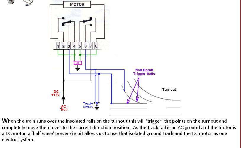
Tortoise Switch Machine Non-Derail | O Gauge Railroading On ...

Lenz LZV100 Command Station


Comments
Post a Comment