39 block diagram reduction examples
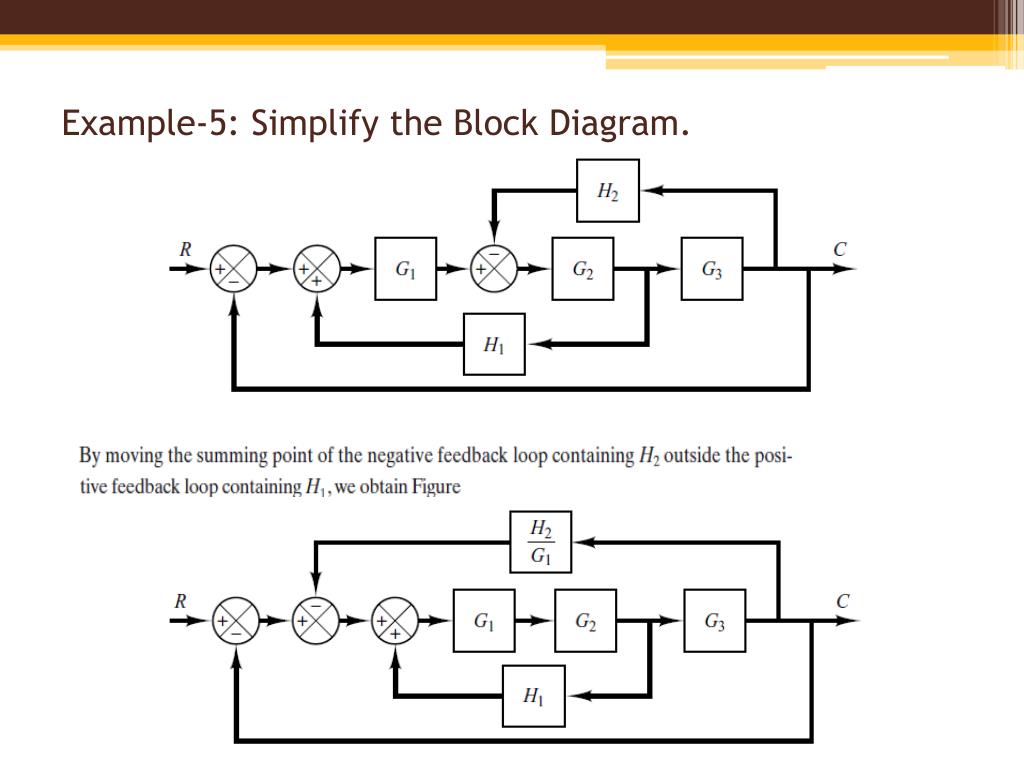
ing block diagrams using block diagram algebra, in addition to the three basic rules described in part A (Figs 2 to 4), various numbers of other rules are introduced in various textbooks with regard to the relocation of the summing/pickoff point(s). Each rule involves a pair of equivalent block diagram. For example, Fig. 5 lists some of the ... Block Diagram Reduction W.3 4Mason™s Rule and the Signal-Flow Graph A compact alternative notation to the block diagram is given by the signal-⁄ow graph introduced Signal-⁄ow by S. J. Mason (1953, 1956). As with the block diagram, the signal-⁄ow graph o⁄ers a visual tool for graph
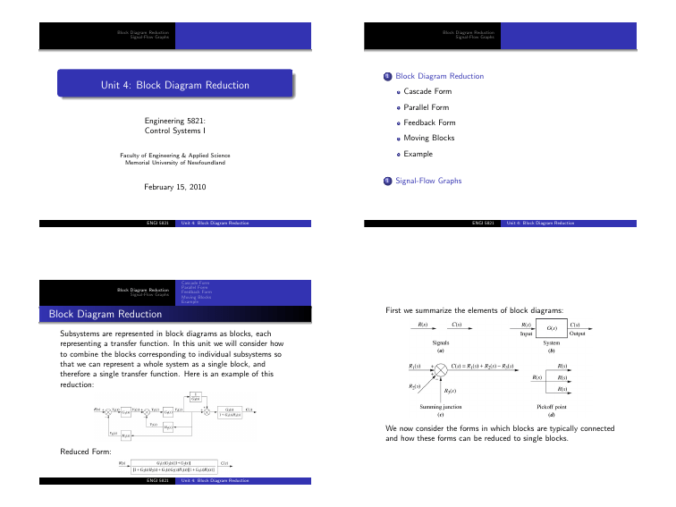
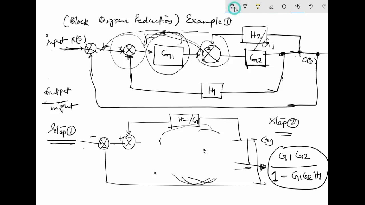
The block diagram reduction process uses more time for complicated systems. The reasons might be need to draw the (partially simplified) block diagram after each step. To overcome this you need use signal flow graphs (representation).

Block diagram reduction examples
160 BLOCK DIAGRAM ALGEBRA AND TRANSFER FUNCTIONS OF SYSTEMS [CHAP. 7 Let the - 1 block be absorbed into the summing point: Step 4c Step 5: By Equation (7.3), the output C, due to input U is C, = [G2/(1 + G1G2)]U. The total output is C=C,+C,= [ ~ 1 +G2G2] [ A] [ A] IGIR + 7.8 REDUCTION OF COMPLICATED BLOCK DIAGRAMS The block diagram of a practical feedback control system is often quite complicated. In order to move the take-off point behind the block, we need to keep the value of 'p' same. Here p = X (s)G (s). But with backward movement p will become X (s). So, we have to add another block with the same gain as the original gain. This will make the value of p = X (s)G (s) Shifting of Summing point ahead of the block Block Diagram • It represents the structure of a control system. • It helps to organize the variables and equations representing the control system. It is composed of: • boxes, that represents the components of the system including their causality; • Lines with arrows, that represent the actual
Block diagram reduction examples. •A Block Diagram is a shorthand pictorial representation of the cause-and-effect relationship of a system. •The interior of the rectangle representing the block usually contains a description of or the name of the element, gain, or the symbol for the mathematical operation to be performed on the input to yield the output. Superposition of Multiple Inputs: To nd the total response in the case of multiple inputs: 1 Set all inputs except one equal to zero. 2 Transform the block diagram to canonical form, using the reduction techniques. 3 Calculate the response due to the chosen input acting alone. 4 Repeat step 1 to 3 for the other remaining inputs. 5 Algebraically add all of the responses (output) obtained in ... Block Diagram Reduction 1 Emam Fathy Department of Electrical and Control Engineering ... Introduction •A Block Diagram is a shorthand pictorial representation of the cause-and-effect relationship of a system. •The interior of the rectangle represent the mathematical ... Example-9: Simplify the block diagram then obtain the close-loop ... Block Diagram Reduction Examples Example 1: R.C. Dorf and R.H. Bishop, Modern Control Systems, 11th Ed., Pearson Prentice-Hall, 2008. Given: The system shown in the block diagram has one input signal, Rs(), and one output signal, Ys(). Find: Using block diagram reduction, find the transfer function () Y s R. Solution:
K. Webb ESE 499 3 Block Diagrams In the introductory section we saw examples of block diagrams to represent systems, e.g.: Block diagrams consist of Blocks - these represent subsystems - typically modeled by, and labeled with, a transfer function Signals - inputs and outputs of blocks - signal direction indicated by arrows - could be voltage, velocity, force, etc. Block diagram of a system. Example Problems and Solutions 115 . Figure 3-45 Reduction of the block diagram shown in Figure 3-44. Figure 3-46 Block diagram of a system. Solution. The block diagram of Figure 3-44 can be modified to that shown in Figure 3-45(a). The above block diagrams of control system output can be rewritten as The above equation can be represented by a block of transfer function G (s) and input R (s) ± X (s)/G (s) again R (s)±X (s)/G (s) can be represented with a summing point of input signal R (s) and ± X (s)/G (s) and finally it can be drawn as below. Block diagram reduction technique . Because of their simplicity and versatility, block diagrams are often used by control engineers to describe all types of systems. A block diagram can be used simply to represent the composition and interconnection of a system. Also, it can be used, together with transfer functions, to represent the cause-and ...
Block Diagram Reduction Figure 1: Single block diagram representation Figure 2: Components of Linear Time Invariant Systems (LTIS) ... In this example, the sign changes twice in the first column so the polynomial equation A(s) = 0 has two roots with positive real parts. Block diagram reduction examples pdf of the schematic drawings in question. Note: The diagram of 1S17.21 (A2) must be printed on solid film. The drawings of the 2N12.4 (A1A, A3, and A4) must be printed from solid paper without insulating tape or metal sheeting. These diagrams provide a rough view of the schematic drawings. As a block diagram we can represent the system by F (s) W(s) X (s) Fig. 1. Block diagram for a system with transfer function W(s). Sometimes we write the formula for the transfer function in the box representing the system. For the above example this would look like F (s) 1 ms2 + bs+ k X (s) Fig. 2. Block diagram giving the formula for the ... A block diagram's transfer function is created using several block diagram reduction rules. A demonstration of MATLAB's feedback and series commands is also ...
Block Diagram Reduction Shortcut Rules In Control System
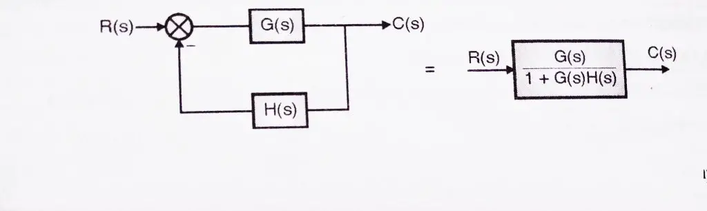
The equivalent block diagram is shown below. Similarly, you can represent the positive feedback connection of two blocks with a single block. The transfer function of this single block is the closed loop transfer function of the positive feedback, i.e., $\frac{G(s)}{1-G(s)H(s)}$ Block Diagram Algebra for Summing Points

To Perform A Block Diagram Reduction Using Matlab Matlab Examples
Block diagram reduction examples Now we will see some block diagram reduction examples. We will start with some simple examples and then will solve a few complex ones. Example 1: In the below example, all the three blocks are in series (cascade). We just need to multiply them as G1(s)×G2(s)×G3(s).
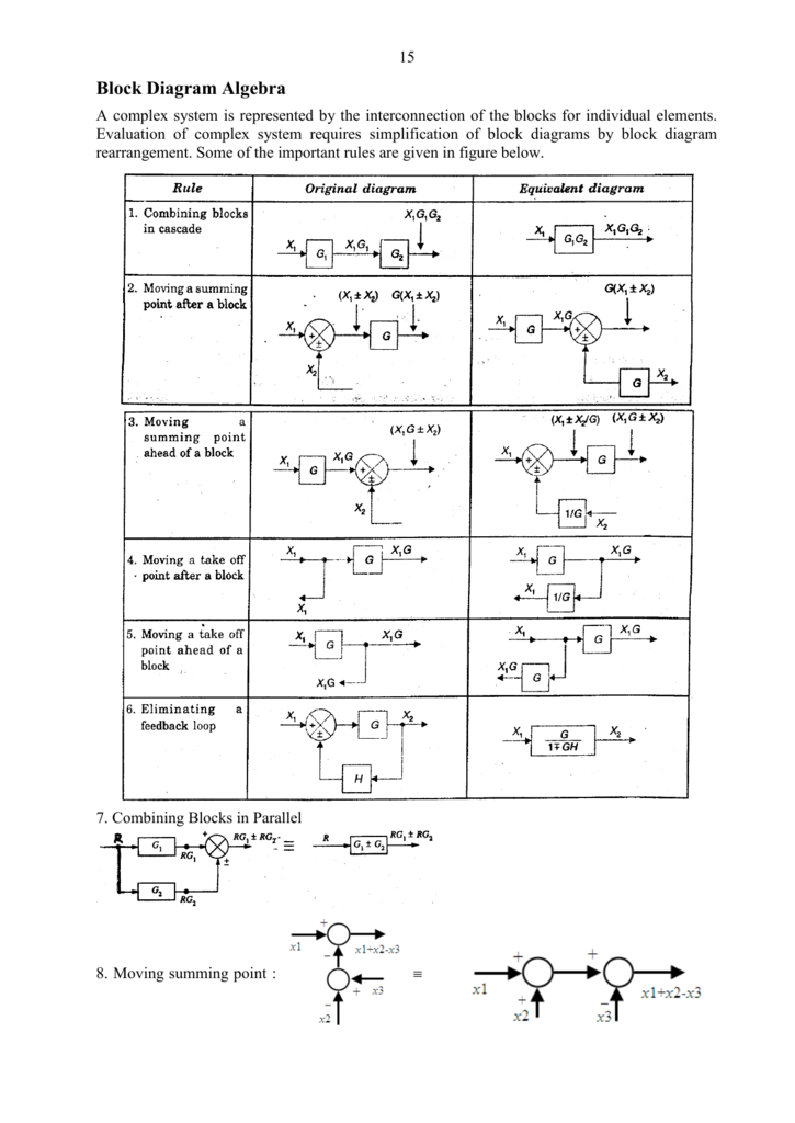
Block Diagram Algebra
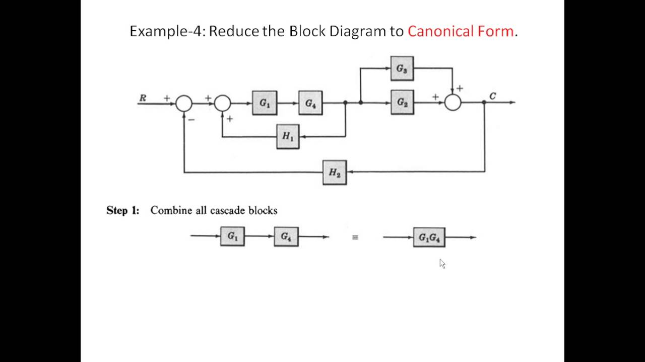
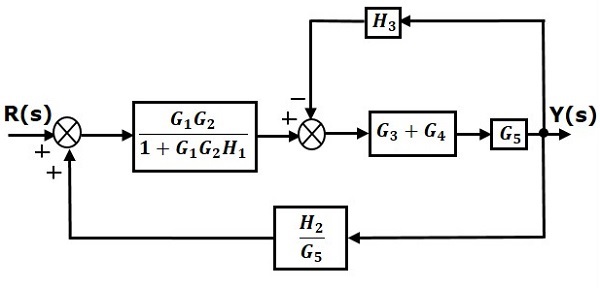
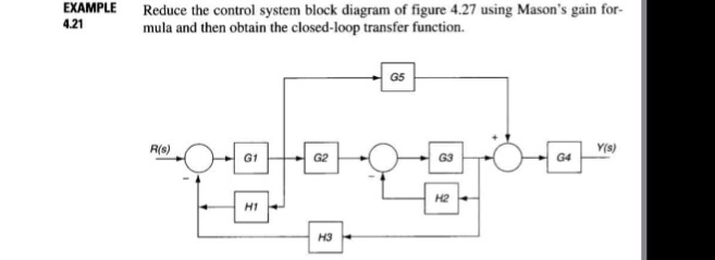
Let us simplify (reduce) this block diagram using the block diagram reduction rules. Step 1 − Use Rule 1 for blocks G 1 and G 2. Use Rule 2 for blocks G 3 and G 4. The modified block diagram is shown in the following figure. Step 2 − Use Rule 3 for blocks G 1 G 2 and H 1. Use Rule 4 for shifting take-off point after the block G 5.
Lect5 Block Diagram Reduction 1 Youtube
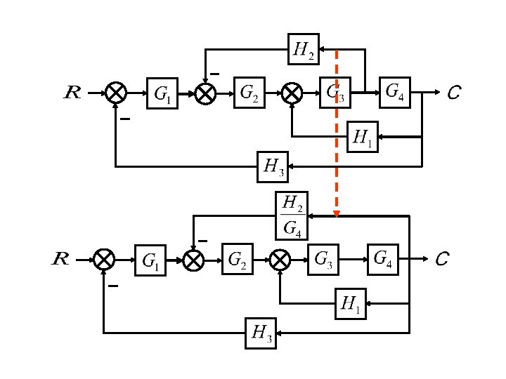
Consider the block diagram shown in the following figure. Let us simplify (reduce) this block diagram using the block diagram reduction rules. Reduction. all steps for block diagram reduction for a complex block diagram. Eliminate loop I & simplify as GGG + B 1G 2H)(sY 4G 2G 1H AB 3G. Visual algebra: use block diagram manipulation instead of ...
Example Of Block Diagram Reduction Rules 5 Electronics Coach
Control Systems: Block Diagram Reduction (Solved Example 1)Topics discussed:1. Solved Example based on the calculation of the overall transfer function of a ...

Aero 371 Lecture 2 Ch 2 6 Block Diagram Oneclass
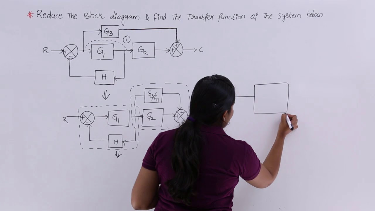
Moving a summing point beyond of a block : Moving a summing point ahead of a block : Let us take an example. EXAMPLE : Using the block diagram reduction technique, find the transfer function of the control system represented by the following block diagram. SOLUTION : Can be solved in following steps by applying above reduction rules .
Block Diagram Reduction Block Diagram Reduction
Block Diagram Reduction Figure 1: Single block diagram representation Figure 2: Components of Linear Time Invariant Systems (LTIS) ... Example 2 Find the transfer function of the following block diagrams G 2 G 1 G 3 G 4 H 1 H 2 Y (s) R(s) 1. Moving pickoff point A ahead of block G 2 2. Eliminate loop I & simplify

Example Of Block Diagram Reduction Pdf
Block diagram Examples. 1. Control System Engineering Kuntumal Sagar M. B.TECH (E.E) UID-U41000000484 Email: skuntmal@yahoo.com TOPIC BLOCK DIAGRAM EXAMPLES. 2. Example 9 Find the transfer function of the following block diagrams 2G 3G1G 4G 1H 2H ) (sY) (sR. 3. 1. Moving pickoff point A ahead of block 2G 2.
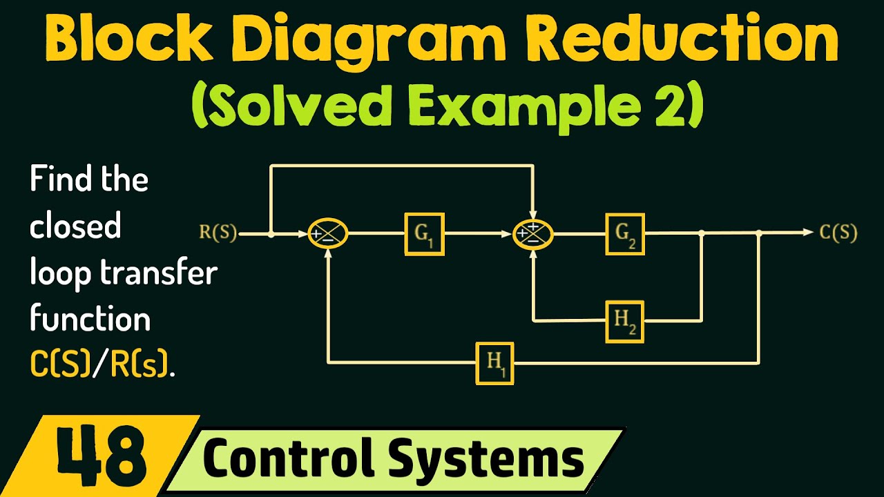
Block Diagram Reduction Solved Example 2 Youtube
Block Diagram Reduction techniques 2G1G 21GG 2. Moving a summing point behind a block G G G 1G 2G 21 GG + 1. Combining blocks which are in cascade or in parallel. 5. 5. Moving a pickoff point ahead of a block G G G G G 1 G 3. Moving a summing point ahead of a block G G G 1 4. Moving a pickoff point behind a block.

Block Diagram Reduction Rules Pdf Mathematical Relations Algorithms
TITLE: Block Diagram Reduction. 1. OBJECTIVE:-. The objective of this exercise will be to learn commands in MATLAB that would be used to reduce linear systems block diagram using series, parallel and feedback configuration. 2. List of Equipment/Software. · Following equipment/software is required: · MATLAB.
Block Diagram Reduction Mathematics Stack Exchange
BLOCK DIAGRAM REDUCTION Block diagram is a pictorial representation of a control system showing inter-relation between the transfer function of various components. The block diagram is obtained after obtaining the differential and transfer function of all components of a control system. Figure 2.1 shows an element of the block diagram.
Problem 1 On Block Diagram Reduction Youtube
Introduction to Block Diagrams Basics of Block Diagrams Examples of Block Diagram Simplifications Module 4 Outline 1 Introduction to block diagrams 2 Physical meaning and importance 3 Block diagram reduction 4 Examples -Reading material: Dorf & Bishop, Section 2.6
2 2 Transfer Function And Impulseresponse Function 2
Block Diagram • It represents the structure of a control system. • It helps to organize the variables and equations representing the control system. It is composed of: • boxes, that represents the components of the system including their causality; • Lines with arrows, that represent the actual

Solve By Block Diagram Reduction R S Cis Gi Homeworklib
In order to move the take-off point behind the block, we need to keep the value of 'p' same. Here p = X (s)G (s). But with backward movement p will become X (s). So, we have to add another block with the same gain as the original gain. This will make the value of p = X (s)G (s) Shifting of Summing point ahead of the block
Control Systems Block Diagram Reduction
160 BLOCK DIAGRAM ALGEBRA AND TRANSFER FUNCTIONS OF SYSTEMS [CHAP. 7 Let the - 1 block be absorbed into the summing point: Step 4c Step 5: By Equation (7.3), the output C, due to input U is C, = [G2/(1 + G1G2)]U. The total output is C=C,+C,= [ ~ 1 +G2G2] [ A] [ A] IGIR + 7.8 REDUCTION OF COMPLICATED BLOCK DIAGRAMS The block diagram of a practical feedback control system is often quite complicated.
Example Of Block Diagram Reduction Rules 4 Electronics Coach

Example Of Block Diagram Reduction Pdf
Zfc Tvuxjskgtm

File Moving Summing Junction Beyond Block 2 Svg Wikimedia Commons
Ebook Dynamic System Modeling And Control

Block Diagram Wikipedia
Block Diagram Reduction Techniques Transfer Function
Wescott Design Services Using Block Diagrams
Uotechnology Edu Iq

For Cascaded Block In Block Diagram Reduction Process The Transfer Function Should Be The Difference Of Homeworklib

Block Diagram Reduction Electrical Simple
1

Block Diagram Simplification Rules Equivalents Process Control Solved Problems Msubbu
Solved Example 4 21 Reduce The Control System Block Diagram Chegg Com
Block Diagram Reduction Of Closed Loop Control Systems Solved Examples Youtube
2 10 Block Diagram Reduction Engineering360

Block Diagram Reduction Method Applied On Example 2 Complete Solution By Engr Syed Ather Rizvi

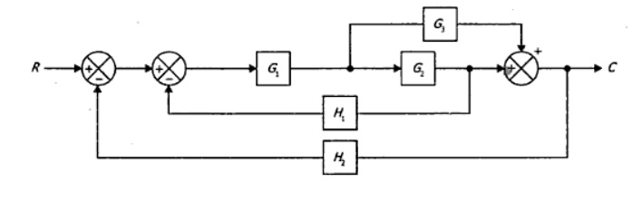
42 Block Diagram Reduction 421 Control Systems With Multiple Loops Control Engineering
Ebook Block Diagram Reduction Examples Ppt Ebook Library
Block Diagram Reduction Mathematics Stack Exchange

Closed Loop System And Closed Loop Control Systems
Feng Stafpu Bu Edu Eg
Ppt Block Diagram Fundamentals Reduction Techniques Powerpoint Presentation Id 6200501
Uotechnology Edu Iq


Comments
Post a Comment